Что представляет собой система управления скважиной на буровой установке?
Apr 16, 2025
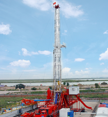
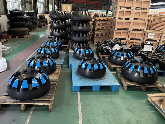
The система управления скважиной буровой установки является важнейшим устройством для обеспечения безопасности буровых работ. Ниже приводится подробное введение в его различные компоненты:Ⅰ.Блок противовыбросовых превенторов (BOP)Превентор противовыбросовыйСтруктура: в основном состоит из таких компонентов, как корпус, сборка плашек, боковые двери, штоки поршней и гидравлические цилиндры. Корпус является основным корпусом плашечного противовыбросового превентора, внутри которого установлены такие компоненты, как сборка плашек. Сборка плашек включает в себя полностью открытые плашки и полуоткрытые плашки, которые являются ключевыми компонентами для достижения герметизации устья скважины. Боковые двери используются для установки и снятия сборки плашек. Штоки поршней соединяют сборку плашек и гидравлические цилиндры, передавая гидравлическое давление. Гидравлические цилиндры обеспечивают мощность для перемещения плашек.Принцип работы: Когда необходимо закрыть устье скважины, гидравлическая система впрыскивает масло под высоким давлением в гидравлические цилиндры, толкая поршневые штоки, чтобы заставить плашки двигаться горизонтально. Затем плашки сжимают друг друга в центре устья скважины, чтобы достичь герметизации устья скважины. Полностью открытые плашки полностью герметизируют устье скважины, когда в устье скважины нет бурильной колонны. Полуоткрытые плашки, в зависимости от размера бурильной колонны, захватывают бурильную колонну и герметизируют кольцевое пространство, когда в устье скважины есть бурильная колонна.Характеристики: Имеет надежную герметизацию и может выдерживать относительно высокое давление на устье скважины. Прост в эксплуатации, действует быстро и может управляться дистанционно. Имеет различные типы и спецификации, которые могут адаптироваться к различным условиям работы бурения и комбинациям бурильных колонн.Кольцевой противовыбросовый превенторСтруктура: в основном состоит из таких компонентов, как кольцевой элемент противовыбросового превентора, поршень, корпус и верхняя крышка. кольцевой элемент уплотнения является основным компонентом кольцевого противовыбросового превентора, обычно изготавливается из эластичных материалов, таких как резина, и имеет кольцевую структуру. Поршень расположен под элементом и тесно взаимодействует с ним. Корпус поддерживает элемент и поршень и соединяется с устьем скважины. Верхняя крышка используется для фиксации элемента и герметизации верхнего пространства.Принцип работы: Когда гидравлическое масло попадает в гидравлический цилиндр под поршнем, оно толкает поршень, чтобы тот двигался вверх. Поршень сжимает элемент, заставляя его упруго деформироваться, тем самым захватывая бурильную колонну или герметизируя кольцевое пространство устья скважины. Когда необходимо открыть устье скважины, гидравлическая система сбрасывает гидравлическое давление, и элемент возвращается в свою первоначальную форму под действием собственной упругой силы, и устье скважины открывается.Характеристики: Может адаптироваться к бурильным колоннам разных размеров и форм, включая келли-штанги, бурильные трубы и утяжеленные бурильные трубы. Имеет хорошие уплотнительные свойства и позволяет бурильной колонне двигаться вверх и вниз и вращаться в определенной степени. Однако он не может выдерживать высокое давление в течение длительного времени, а элемент подвержен износу и требует регулярной замены.Вращающийся противовыбросовый превенторСтруктура: в основном состоит из таких компонентов, как вращающийся узел, вращающийся уплотнительный элемент противовыбросового превентора, корпус, подшипники и гидравлическая система управления. Вращающийся узел включает в себя такие компоненты, как вращающийся вал, вращающаяся головка и соединительные фланцы, которые являются компонентами для вращения бурильной колонны. Уплотнительный элемент используется для герметизации кольцевого пространства между бурильной колонной и устьем скважины. Корпус поддерживает вращающийся узел и уплотнительный элемент и соединяется с устьем скважины. Подшипники устанавливаются между вращающимся валом и корпусом для обеспечения плавного вращения вращающегося узла. Гидравлическая система управления используется для управления захватом и освобождением уплотнительного элемента.Принцип работы: В процессе бурения бурильная колонна соединяется с вращающимся противовыбросовым превентором через вращающийся узел. Когда необходимо контролировать давление на устье скважины, гидравлическая система подает давление на уплотнительный элемент, заставляя элемент захватывать бурильную колонну и достигать уплотнения устья скважины. В то же время вращающийся узел, поддерживаемый подшипниками, может вращаться вместе с бурильной колонной, обеспечивая нормальный ход операции бурения.Характеристики: Позволяет бурильной колонне вращаться и двигаться вверх и вниз под давлением, повышая эффективность бурения. Имеет надежную герметизацию и может выдерживать определенное давление на устье скважины. Однако его конструкция сложна, а требования к техническому обслуживанию относительно высоки.Ⅱ.Дроссельный коллектор и коллектор глушенияДроссельный коллекторСтруктура: в основном состоит из таких компонентов, как штуцерные клапаны, плоские клапаны, трубопроводы, манометры и термометры. Штуцерный клапан является основным компонентом штуцерного манифольда, используемого для регулирования расхода и давления бурового раствора. Плоский клапан используется для управления открытием и закрытием трубопровода. Трубопроводы соединяют все компоненты, образуя канал потока бурового раствора. Манометры и термометры используются для контроля давления и температуры бурового раствора в штуцерном манифольде.Принцип работы: При управлении скважиной, путем регулировки степени открытия штуцера, изменяется площадь потока бурового раствора, тем самым контролируя расход бурового раствора и противодавление на устье скважины. Когда давление на устье скважины повышается, степень открытия штуцера уменьшается, чтобы увеличить противодавление на устье скважины, в результате чего забойное давление повышается и уравновешивает пластовое давление. Когда давление на устье скважины падает, степень открытия штуцера увеличивается, чтобы уменьшить противодавление на устье скважины и предотвратить слишком высокое забойное давление, которое может привести к потере циркуляции.Характеристики: Дроссельный клапан имеет хорошую производительность дросселирования и точность регулировки, что позволяет точно контролировать расход и давление бурового раствора. Плоский клапан имеет хорошую производительность уплотнения и может выдерживать относительно высокое давление. Дроссельный коллектор имеет различные методы соединения и спецификации и может быть выбран в соответствии с различным буровым оборудованием и условиями работы.Убить МанифолдСтруктура: в основном состоит из таких компонентов, как насос глушения, обратный клапан, предохранительный клапан, трубопроводы и манометры. Насос глушения является основным оборудованием коллектора глушения, используемым для закачки жидкости глушения в скважину. Обратный клапан предотвращает обратный поток жидкости глушения. Предохранительный клапан используется для защиты коллектора глушения и оборудования устья скважины и предотвращения слишком высокого давления. Трубопроводы соединяют все компоненты, образуя транспортировочный канал жидкости глушения. Манометры используются для контроля давления в коллекторе глушения.Принцип работы: В случае выброса или выброса в первую очередь устье скважины противовыбросовый превентор закрывается, а затем запускается насос глушения для закачки подготовленной жидкости глушения в скважину через коллектор глушения. Жидкость глушения смешивается с пластовой жидкостью в скважине и постепенно уравновешивает пластовое давление, восстанавливая баланс давления в скважине. Во время операции глушения, регулируя подачу и давление насоса глушения и наблюдая за показаниями манометров, обеспечивается безопасность и эффективность операции глушения.Характеристики: Насос глушения имеет достаточный рабочий объем и давление для быстрой перекачки жидкости глушения в скважину. Обратный клапан и предохранительный клапан обеспечивают безопасность и надежность коллектора глушения. Трубопроводы коллектора глушения обычно используют высокопрочные и коррозионно-стойкие материалы, которые выдерживают высокое давление и суровые условия работы.Ⅲ.Инструменты контроля скважинМонитор уровня в баке бурового раствораСтруктура: в основном состоит из таких компонентов, как датчики, передатчики и индикаторные приборы. Датчики устанавливаются в резервуаре с буровым раствором и используются для измерения высоты уровня жидкости. Передатчики преобразуют сигналы, измеренные датчиками, в стандартные электрические или пневматические сигналы. Индикаторные приборы устанавливаются в операционной или на пульте управления буровой платформы и используются для отображения числового значения и изменения ситуации высоты уровня жидкости.Принцип работы: Датчики измеряют высоту уровня жидкости в резервуаре с буровым раствором с помощью таких принципов, как плавучесть, гидростатическое давление и ультразвуковые волны, и передают измеренные сигналы на передатчики. Передатчики преобразуют сигналы, а затем передают их на дисплейные приборы для отображения. Когда высота уровня жидкости изменяется, числовое значение на дисплее также изменяется соответствующим образом. Оператор может быстро определить, возникают ли в скважине нештатные ситуации, такие как выброс или потеря циркуляции, в соответствии с повышением и понижением уровня жидкости.Характеристики: Высокая точность измерения, возможность точного измерения небольших изменений высоты уровня жидкости. Высокая скорость отклика, возможность оперативного отображения динамических изменений уровня жидкости. Разнообразие методов измерения и форм выходного сигнала, возможность адаптации к различным конструкциям резервуара для бурового раствора и систем управления.Датчик давления стоякаСтруктура: в основном состоит из таких компонентов, как чувствительный к давлению элемент, схема преобразования сигнала и корпус. Чувствительный к давлению элемент обычно использует такие материалы, как тензодатчики и пьезоэлектрические кристаллы, и используется для измерения давления бурового раствора в стояке. Схема преобразования сигнала преобразует слабые электрические сигналы, генерируемые чувствительным к давлению элементом, в стандартные электрические сигналы. Корпус защищает чувствительный к давлению элемент и схему преобразования сигнала от помех и повреждений внешней средой.Принцип работы: Когда давление бурового раствора в стояке воздействует на чувствительный к давлению элемент, чувствительный к давлению элемент деформируется, вызывая изменения его параметров, таких как сопротивление или емкость. Схема преобразования сигнала преобразует эти изменения параметров в электрические сигналы и передает их в систему управления приборами буровой платформы по кабелям. Система управления приборами обрабатывает и отображает полученные электрические сигналы. Оператор может судить о тенденции изменения забойного давления в соответствии с изменением ситуации давления стояка и оперативно корректировать параметры бурения и принимать меры по контролю скважины.Характеристики: Высокая точность измерений, возможность точного отражения изменений давления бурового раствора в стояке. Хорошая стабильность, возможность длительной и стабильной работы в суровых условиях. Хорошая помехоустойчивость, возможность исключения влияния электромагнитных помех на результаты измерений.Датчик давления в корпусеСтруктура: Подобно датчику давления стояка, он в основном состоит из таких компонентов, как чувствительный к давлению элемент, схема преобразования сигнала и корпус. Чувствительный к давлению элемент устанавливается на корпусе устья скважины и напрямую измеряет давление в корпусе. Схема преобразования сигнала преобразует сигнал давления в электрический сигнал. Корпус защищает чувствительный к давлению элемент и схему преобразования сигнала.Принцип работы: Когда давление в обсадной колонне изменяется, чувствительный к давлению элемент воспринимает изменение давления и генерирует соответствующие изменения электрического сигнала. Схема преобразования сигнала преобразует эти изменения в стандартные электрические сигналы и передает их в систему управления приборами буровой платформы по кабелям. Система управления приборами обрабатывает и отображает сигналы. Оператор может судить о величине противодавления устья скважины и о соотношении между забойным давлением и пластовым давлением в соответствии с изменением ситуации давления в обсадной колонне, что обеспечивает важную основу для операций по управлению скважиной.Характеристики: Высокая точность и надежность измерений, возможность точного измерения изменений давления в обсадной колонне. Простота установки, возможность установки непосредственно на обсадной колонне устья скважины. Хорошая герметичность, предотвращение утечки жидкости в обсадной колонне.Ⅳ.Система управленияГидравлическая система управленияСтруктура: в основном состоит из таких компонентов, как гидравлическая станция, трубопроводы управления, направляющие клапаны управления, предохранительные клапаны и аккумуляторы. Гидравлическая станция включает в себя такие компоненты, как масляный насос, двигатель, масляный бак и фильтр, которые используются для обеспечения гидравлической мощности. Управляющие трубопроводы соединяют гидравлическую станцию с такими устройствами, как противовыбросовый превентор, дроссельный коллектор и коллектор глушения, для передачи гидравлического масла. Направляющие клапаны управления используются для управления направлением потока гидравлического масла для достижения управления действием каждого устройства. Предохранительные клапаны используются для регулирования давления в системе и предотвращения слишком высокого давления. Аккумуляторы используются для хранения гидравлической энергии и обеспечения дополнительной мощности для системы в случае чрезвычайной ситуации.Принцип работы: двигатель приводит в действие масляный насос для извлечения гидравлического масла из масляного бака, нагнетает его, а затем транспортирует его к каждому гидравлическому устройству через трубопроводы управления. Когда необходимо управлять действием определенного устройства, путем управления направляющим регулирующим клапаном направление потока гидравлического масла изменяется, и гидравлическое масло поступает в гидравлический цилиндр соответствующего устройства, толкая поршень для перемещения и осуществляя открытие или закрытие устройства. Предохранительный клапан автоматически регулирует расход гидравлического масла в соответствии с давлением в системе, чтобы поддерживать давление в системе стабильным. Когда давление в системе падает, аккумулятор высвобождает накопленную гидравлическую энергию для пополнения давления в системе и обеспечения нормального действия устройства.Характеристики: Гидравлическая система управления имеет преимущества быстрой скорости реагирования, высокой точности управления и большой выходной силы, а также может быстро и точно управлять действиями устройств управления скважиной. Она имеет хорошую надежность и стабильность и может стабильно работать в течение длительного времени в суровых рабочих условиях. Приняты избыточные меры по проектированию и защите безопасности, которые повышают безопасность и отказоустойчивость системы.Пульт дистанционного управленияСтруктура: в основном состоит из таких компонентов, как корпус пульта, экран дисплея, кнопки управления, схема управления и система электропитания. Корпус пульта является основным компонентом пульта дистанционного управления, внутри которого установлены схема управления и различные электронные компоненты. Экран дисплея используется для отображения информации о состоянии устройств управления скважиной, данных о давлении и т. д. Кнопки управления используются для дистанционного управления действиями устройств управления скважиной. Схема управления управляет действиями гидравлической системы управления или других приводов в соответствии с инструкциями по эксплуатации оператора. Система электропитания обеспечивает электропитание пульта дистанционного управления и обычно оснащена резервным источником питания, таким как аккумуляторная батарея.Принцип работы: Оператор выдает команды управления, нажимая кнопки на пульте дистанционного управления. Схема управления преобразует команды в электрические сигналы и передает их в гидравлическую систему управления или другие исполнительные механизмы по кабелям или беспроводным методам связи. Гидравлическая система управления управляет действиями устройств управления скважиной в соответствии с полученными сигналами. В то же время информация о состоянии и данные о давлении устройств управления скважиной собираются датчиками и передаются на экран дисплея пульта дистанционного управления для мониторинга оператором в режиме реального времени. В случае возникновения чрезвычайной ситуации автоматически включается резервный источник питания для обеспечения нормальной работы пульта дистанционного управления.Характеристики: Пульт дистанционного управления реализует удаленное управление и мониторинг устройств управления скважиной, повышая безопасность и удобство операций управления скважиной. Он имеет хороший интерфейс взаимодействия человек-машина, а операция проста и интуитивно понятна. Он имеет функцию записи и хранения данных и может записывать и анализировать данные в процессе операции управления скважиной, обеспечивая основу для последующего расследования и устранения аварий.
ЧИТАТЬ ДАЛЕЕ


 Language :
 Русский
 English
 عربي
عربي
 Получить предложение


 IPv6 ПОДДЕРЖИВАЕТСЯ СЕТЬЮ